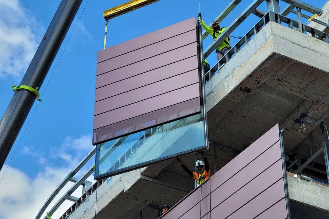
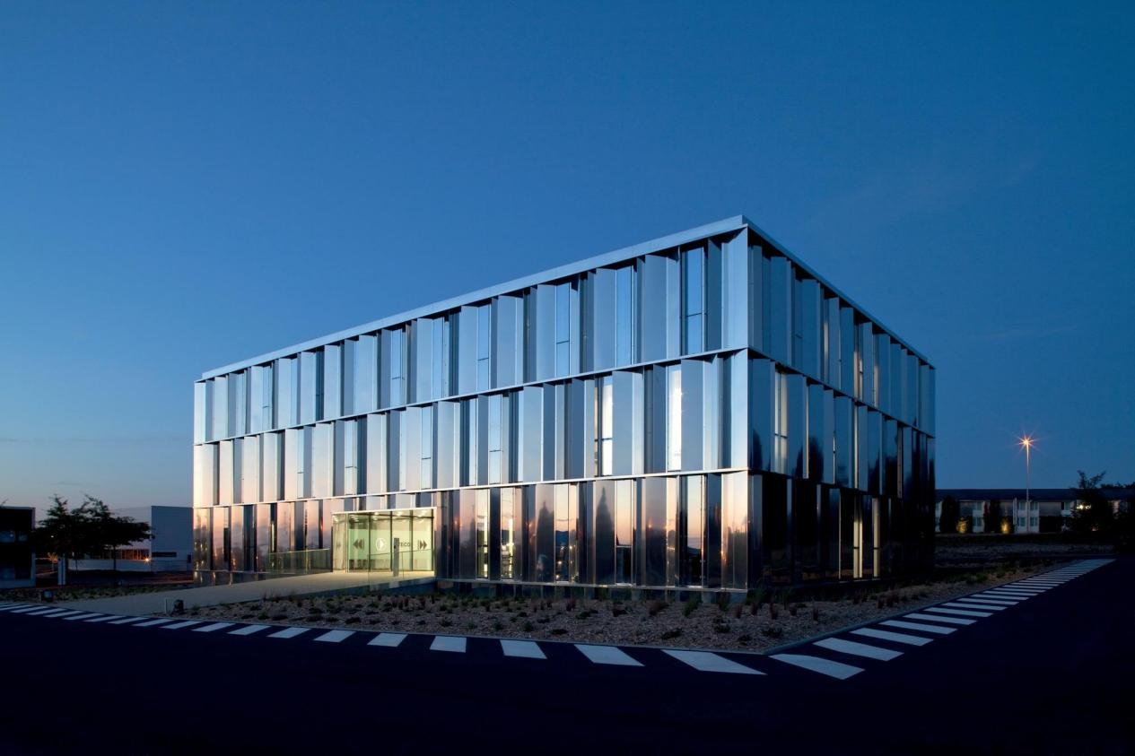
A window shift, corner return, or uneven facade bay can disrupt an otherwise regular metal panel layout. The result may be a narrow panel beside an opening, offset joint lines between elevations, or a termination that looks accidental rather than designed. These problems often emerge when the design team begins coordinating metal facade panels with actual building dimensions and construction details.
Getting the panel layout right means deciding where joints should run, how panels meet openings, and which dimensions can repeat without creating awkward cuts elsewhere. This article looks at six common layout problems in flat and folded metal panels, particularly solid aluminum panels, and how they can be adjusted before fabrication and installation.
1. Misaligned Joints in Metal Facade Panels

Joint lines can drift between adjacent facade areas even when both use the same panel width. Different starting points, separately developed elevations, or late changes to window positions can leave the grid disconnected at an entrance or corner.
Align Panel Joints with Key Building Lines
Window heads, floor levels, and prominent building edges often give the panel layout its clearest reference points. The designer can use those lines to organize the main panel joints, then make smaller adjustments in less visible areas where needed.
Two elevations, for example, may look balanced on their own but meet with offset horizontal joints. Looking at them together usually makes it easier to see whether the mismatch comes from the starting height or from one panel row that needs to shift.
Intentional staggered joints can still work well when they are part of the design. The issue is a break that looks accidental in a pattern that otherwise appears continuous. Showing the main control lines on the facade elevation makes that easier to judge.
2. Narrow Panels Around Windows and Corners
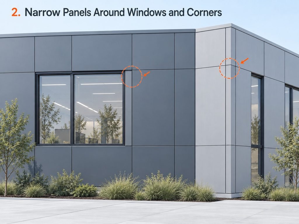
A repeated module rarely fits every opening and boundary without adjustment. Starting with a full panel at one end can leave a thin strip beside a window, while continuing the same grid around a corner may produce an awkward return.
Adjust the Panel Layout Around Openings and Corners
It is usually easier to avoid these narrow pieces while the surrounding panel widths are still flexible. Shifting the layout’s starting point may improve both ends of a wall, while a small dimensional difference can be shared across several adjacent panels instead of being left in one noticeably narrow piece.
Corners can create the same problem from another direction. A grid that looks balanced on one elevation may leave a narrow return when it turns the corner. Small changes to the adjacent panel widths can often improve that condition. If the main joint lines need to stay fixed, a folded corner panel or separate corner trim may provide a cleaner termination, depending on the selected system.
Window heads, sills, and jambs also affect where the surrounding panels can finish. Their visible edges should be coordinated before the nearby panel widths are finalized.
3. Panel Size Limits for Fabrication and Installation

Larger panels reduce the number of visible joints, but their dimensions also affect forming, support, transport, and handling. A panel that the factory can produce may still be difficult to move through the site or position using the available equipment.
Visible panel dimensions are only part of the manufacturing requirement. Folded returns add material beyond the face, so the developed sheet size also needs to be checked before production feasibility is confirmed.
Review Panel Sizes Before Finalizing the Layout
Before the panel layout is finalized, the proposed sizes should be reviewed with the manufacturer or fabricator. The fabrication team can check the developed sheet size and forming requirements, while the installation team can confirm whether the panels can be transported, handled, and positioned on site. The support design also needs to accommodate the proposed format.
If a panel exceeds the confirmed fabrication or handling limits, the manufacturer may recommend reducing one dimension, adjusting the panel proportions, or dividing the panel. The design team can then work that change back into the elevation rather than adding a joint wherever space happens to be available. A window line or another architectural break can often provide a more natural place for the split.
Also consider flatness expectations before fixing large panel sizes in the layout, especially where broad surfaces dominate the elevation. Maximum panel sizes vary by product and system, so do not transfer a limit from one product directly to another.
4. Inconsistent Panel Widths Across Repeated Facade Areas

A facade may need different panel sizes around windows, corners, and other building conditions. The problem is when repeated areas begin using slightly different panel widths without a clear layout reason. These small changes can break the visual rhythm of the elevation and leave the panel schedule with more variations than the design actually requires.
Keep Panel Widths Consistent Across Repeated Areas
Repeated facade areas should be reviewed together rather than adjusted one by one. Where the building conditions are similar, keeping the same panel widths can create a more consistent layout and make the panel schedule easier to coordinate. Special sizes can remain where openings, corners, or deliberate design features genuinely require them.
Material efficiency can still be considered when the panel dimensions are finalized, since the finished sizes affect how parts fit within available sheet sizes. It should not drive the layout, however. A dimension that improves sheet usage but creates an awkward cut at a visible boundary may not be the better choice.
5. Panel Layout Conflicts with Supports and Fixings

A panel layout can look correct on the elevation and still create problems once the subframe and fixing locations are checked. This often happens when the panel layout and support system are developed separately.
The simplest way to catch the conflict is to review the panel arrangement together with the approved support and fixing locations. If a panel boundary can move slightly without disturbing the main alignment lines, adjusting the layout is usually the easier option.
Some architectural joints, however, need to stay where they are. In those areas, the responsible designer may need to adjust the supporting detail instead of moving the panel joint. Corners and openings also need enough access for installers to reach the connections.
Once those changes are agreed, they should be reflected in the coordinated shop drawings so the panel supplier and installer are working from the same layout.
6. Facade Panel Joint Gaps and Movement Allowance

Very tight facade panel joints can look attractive in a rendering, but they still need enough room for temperature-related movement and dimensional variation on site. A joint chosen mainly for appearance may leave too little clearance for the system to work as intended.
The manufacturer and responsible designer should set the joint dimensions around the selected material, panel size, fixing arrangement, and project conditions. Once that gap becomes part of the repeating layout module, even a small change in joint width can affect the panel dimensions or panel count across the facade.
Site measurements may also show that the available run differs from the original layout. In that case, selected panel widths or permitted connection adjustments can be used to take up the difference without reducing the required joint clearance.
Building movement joints still need separate coordination; ordinary panel gaps do not replace them.
Final Checks Before Metal Facade Panel Fabrication

A workable metal facade panel layout has to do more than create a clean pattern on the elevation. Joint lines need to stay coordinated across openings and corners, panel sizes must remain practical for fabrication and handling, repeated areas need a clear dimensional logic, and the layout has to work with the approved supports and required joint gaps.
Most of these issues are easier to solve while panel widths, joint positions, and interface details are still adjustable. Once the layout moves into production, even a small change can affect panel schedules, shop drawings, fabrication, and installation.
PRANCE design team can help to support the transition through site measurement, design development, and production, helping turn the coordinated facade layout into panel drawings and fabrication-ready information. For projects approaching production, contact PRANCE to discuss the facade layout and next-stage design support.
Metal Facade Panel Layout FAQs
Can metal facade panels use different sizes in the same layout?
Yes. Mixed sizes can respond to openings or create a deliberate facade pattern. The size changes need a clear visual logic, with joints coordinated across the different modules.
Can an existing facade layout be reused for replacement panels?
An existing layout can provide a starting point, but the replacement design needs verified dimensions and an assessment of the retained supports. New panels may use different edge details, joint widths, or fixing methods. Original drawings alone cannot confirm compatibility, particularly where previous repairs or site alterations have changed the facade.
Who reviews the panel layout before fabrication?
Review typically involves the architect or facade designer, panel manufacturer, and installation contractor, with the responsible engineer addressing structural support and connection design. Their involvement depends on the project contract. Each party should be clear about who confirms the appearance, verifies site dimensions, resolves technical interfaces, and approves the drawings for production.
Can one damaged panel be replaced without removing adjacent panels?
Individual replacement is possible when the chosen system allows a panel to be detached and removed with its neighbors in place. The installer needs clear access to the fixings and enough room to remove the panel. If neighboring panels or trims cover those connections, their removal becomes part of the replacement sequence. Retaining panel identification and fabrication records also helps the owner order a suitable replacement.