

Custom metal ceiling manufacturing starts with an architectural ceiling plan, but production also depends on detailed fabrication drawings. Before panels enter the factory, the approved design must be developed into drawings that specify panel sizes, joints, openings, support conditions, finishes, and other manufacturing requirements.
A complete drawing package also helps architects and contractors identify unresolved interfaces before they become site problems, while giving procurement teams a clearer basis for quantities, finishes, custom components, and production approval.
This article outlines the essential drawing information required for custom metal ceiling projects, including panel dimensions, joint layouts, openings, support conditions, finishes, and other fabrication details.
Fabrication Drawings Prepared by the Metal Ceiling Manufacturer
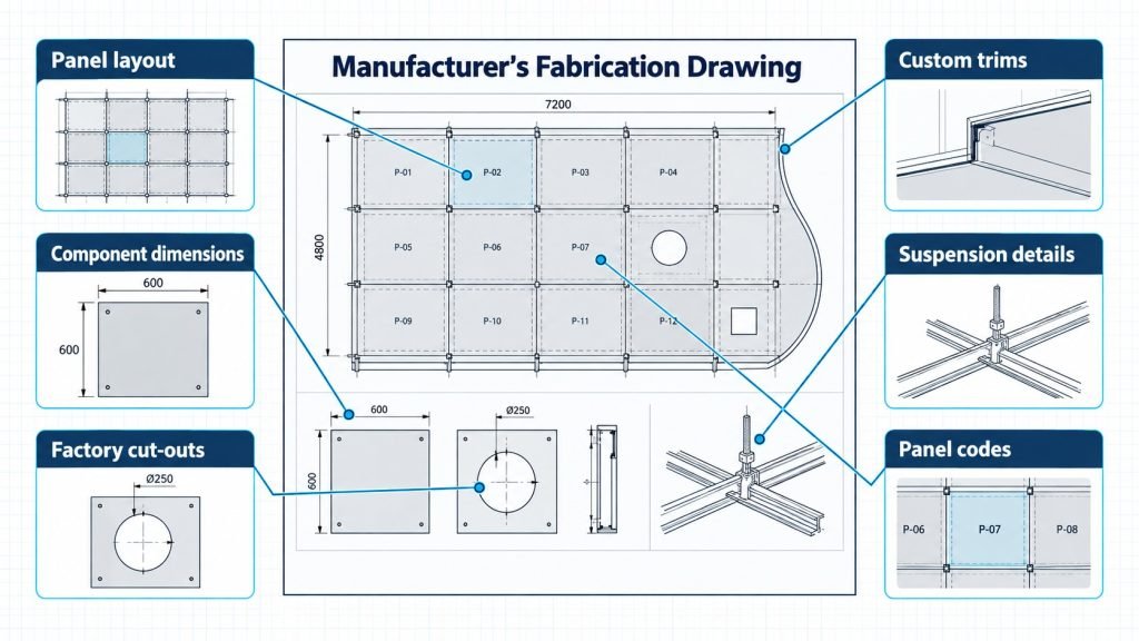
The metal ceiling manufacturer normally prepares six categories of fabrication information from the approved RCP, coordinated MEP locations, confirmed finishes, and relevant site dimensions. Depending on the project, several categories may be combined on the same drawing sheet.
|
Manufacturer’s Document |
When It Is Needed |
Production Information |
|
Production panel layout |
Most custom metal ceilings |
Modules, joints, orientation, perimeter panels |
|
Panel and component drawings |
Custom panels, trims, profiles, or brackets |
Dimensions, folds, cut-outs, perforations |
|
Section and interface details |
Perimeters, transitions, and level changes |
Edges, joints, trims, connections |
|
Suspension and support details |
When included in the manufacturer’s scope |
Carriers, spacing, levels, fixing positions |
|
Factory opening details |
Panels with coordinated MEP openings |
Opening sizes, center points, panel references |
|
Panel and finish schedule |
Multiple panel types or finishes |
Codes, materials, thicknesses, quant |
Production Panel Layouts
The manufacturer develops the production panel layout from the approved architectural RCP and coordinated ceiling information. The layout defines the ceiling zones, panel modules, joint positions, panel orientation, perimeter conditions, and panel identification required for production.
In irregular ceiling areas, the architectural plan may show the intended visual grid without identifying every unique perimeter or transition panel.
Panel and Custom Component Fabrication Drawings
Individual fabrication drawings provide the component-level information required by the factory. They may show panel dimensions, edge returns, folds, fixing points, holes, cut-outs, perforation patterns, and connection geometry.
Factory-made trims, transition profiles, brackets, and other custom components also need corresponding fabrication information. Each part should be linked to the production panel layout through a consistent component code.
Sections, Joints, and Interface Details
Plan drawings cannot fully describe every ceiling condition. Based on approved architectural details and confirmed interface conditions, the manufacturer prepares sections and details where the supplied ceiling panels meet walls, columns, bulkheads, other ceiling systems, or changes in level.
They can also reveal where the design module does not fit the available space. Resolving these interfaces before fabrication reduces the need to modify finished panels on site.
Suspension and Support Details
Where the suspension system is included in the manufacturer’s supply scope, fabrication drawings can identify carriers, hangers, support spacing, ceiling levels, and fixing positions within the supplied ceiling system.
The suspension drawing should account for panel joints, perimeter conditions, MEP services, and other building elements that affect the support layout.
Factory Cut-Out and MEP Opening Details
The project team should coordinate and confirm the positions of lights, diffusers, sprinklers, speakers, detectors, and access openings. The manufacturer then translates the approved locations into panel-level production details.
For factory-made openings, the fabrication drawing should define the opening size, center point, panel reference, and any required edge or support detail. Final service positions need to be confirmed before the affected panels are released for fabrication.
Panel, Material, and Finish Schedules
Not every production requirement belongs on the face of a drawing. A panel or material schedule can connect each drawing reference with its approved material, thickness, finish, perforation, quantity, and other specified characteristics.
Panel identification becomes particularly useful when a ceiling contains many unique sizes or directional finishes. Clear codes allow fabrication drawings, production quantities, packing information, and site locations to reference the same component consistently.
Shop Drawings vs. Fabrication Drawings for Metal Ceilings

Metal ceiling shop drawings normally coordinate how the complete ceiling fits the project. Depending on the contract and responsibility structure, the specialist contractor, ceiling supplier, or manufacturer may prepare them. The drawings can show the overall layout, ceiling levels, panel modules, perimeter conditions, suspension arrangement, MEP services, and architectural interfaces.
Once the relevant shop drawings and project information are coordinated, the metal ceiling manufacturer prepares fabrication drawings for the exact panels and components the factory will produce. These drawings define dimensions, bends, edge details, holes, perforations, cut-outs, connection geometry, and component codes.
For a simple repetitive ceiling, shop drawing and fabrication information may appear in the same drawing set. Custom shapes, complex interfaces, large-format panels, or extensive MEP integration usually require additional component-level details. Shop drawing approval establishes a coordination baseline, but fabrication still requires an authorized production release.
Information the Manufacturer Needs Before Production Started

Before manufacturing begins, the manufacturer should confirm that all approved inputs affecting fabrication have been received:
-
- Approved geometry: The current approved RCP, ceiling levels, control lines, panel modules, relevant architectural details, and verified site-dependent dimensions should be available for production. Perimeter panels or transitions may remain unreleased until the required dimensions are confirmed.
-
- Coordinated MEP openings and access: Final opening sizes, center points, relationships with panel joints, and access arrangements should be confirmed by the responsible project parties. The manufacturer uses this information to prepare the affected panel details.
-
- Approved materials and appearance: The fabrication package should follow the approved panel material, thickness, finish reference, color, perforation pattern, custom graphic pattern, and surface direction. Drawing and schedule references should match the approved specification, sample, or mock-up.
-
- Confirmed interfaces and supports: Confirmed wall conditions, structural interfaces, edge supports, ceiling transitions, suspension conditions, fixing locations, and installation clearances relevant to the manufacturer’s scope should be available before release.
-
- Panel codes and quantities: Component codes, quantities, finishes, perforation directions, and site locations should remain consistent across the fabrication drawings, schedules, and production information.
-
- Revision and approval status: The manufacturer should receive one clearly identified drawing set authorized for production. Superseded drawings must be separated from the current release package.
If an architectural or MEP change affects a manufactured component, the revised requirement should be confirmed before the manufacturer updates the relevant fabrication drawing for production.
From Approved Fabrication Drawings to Metal Ceiling Production

Production-ready fabrication drawings give the factory clear information for panel geometry, custom components, MEP openings, suspension conditions, materials, finishes, quantities, and revisions. The package is complete when these requirements are resolved clearly enough for the panels, trims, supports, openings, and interfaces to move into production.
For a custom metal ceiling project, share the approved RCP, architectural details, coordinated MEP information, finish requirements, and relevant site conditions with the metal ceiling manufacturer early. This provides a clearer basis for approving fabrication drawings before manufacturing release. If you need support developing production-ready fabrication drawings for a custom metal ceiling project, contact PRANCE design to discuss your drawings, ceiling system, and project requirements.
FAQs
Can Architectural Drawings Be Used Directly for Metal Ceiling Fabrication?
Usually not. Architectural drawings show design intent and overall geometry, but custom metal ceiling production normally requires fabrication-level information such as panel dimensions, edge details, folds, openings, perforations, and component codes.
Can Fabrication Drawings Be Prepared Before Final Site Dimensions Are Available?
Yes. Standard modules can often be developed first, while site-dependent perimeter panels, transitions, or interfaces remain unreleased until dimensions are verified. The project team should identify which dimensions are design-controlled and which require site confirmation before production approval.
Do Custom Perforated Ceiling Panels Need Separate Fabrication Details?
Often, yes, but not always on a separate drawing sheet. Fabrication details may need to define perforation size and layout, non-perforated borders, pattern direction, panel joints, MEP openings, and positioning references for custom patterns.
Who Should Approve Metal Ceiling Fabrication Drawings Before Production?
Approval depends on the project contract and responsibility structure. The architect, contractor, consultant, specialist ceiling contractor, or another authorized party may be involved. The manufacturer should receive a clearly identified production release before fabrication begins.


