Thermal Break Strategies for Aluminum Curtain Walls in Hot and Humid Climates
Introduction
A well-designed thermal break curtain wall is foundational for high-performance façades in hot and humid climates. For projects in Saudi Arabia—where high solar radiation, elevated dew points, and extended cooling seasons drive large HVAC loads—specifying an effective thermal break curtain wall reduces conductive heat transfer, raises interior surface temperatures above dew point, and minimizes condensation-related damage to finishes. This article provides actionable design criteria, testable performance targets, installation and QA procedures, lifecycle economics, and a Saudi Arabia–focused case example for architects, façade engineers, contractors, and owners.
Thermal Break Curtain Wall: Key Technical Features
Thermal Break Curtain Wall: Materials and Profiles
Thermal break systems separate exterior and interior aluminium sections by inserting low-conductivity materials. Common choices:
Encapsulated structural polyurethane — very low conductivity but needs protection from UV/chemicals.
Fiber-reinforced polymer (FRP) composites — used where custom profiles or retrofit geometry are required.
Profile geometry, continuous interlocks, pressure-plate design, and fixings all influence performance. For tall mullions demand documented structural and thermal FEA, and specify movement tolerances (e.g., ±10 mm for high columns) to avoid thermal short-circuits at joints.
Thermal Performance Metrics and Test Methods
Require calibrated metrics and recognized test methods in tender documents:
Whole-frame U-value measured to ASTM C1363 or ISO 15099.
Linear thermal transmittance (ψ-value) at mullion-to-glass and corner details.
Hygrothermal/condensation modeling (e.g., WUFI or EN 15026 workflows) to verify dew point margins.
Also include air- and water-tightness tests (ASTM E283/E1105, EN 12207) to ensure that thermal performance is not undermined by leakage or water ingress.
Design Considerations for Thermal Break Curtain Wall in Hot-Humid Climates
Thermal Break Curtain Wall: Condensation Control Strategies
Condensation control is the prime driver in hot-humid environments. Design goals:
Keep interior face temperatures at least 3°C above indoor dew point under worst-case HVAC settings (e.g., 24°C, 60% RH).
Use multi-layer thermal spacers, thicker polyamide sections, and continuous gasket strategies.
Model seasonal hygrothermal behavior early and coordinate with MEP to avoid overly aggressive setpoints that elevate condensation risk.
Solar Heat Gain, U-values, and Shading Integration
Optimize glazing and frame together:
Target SHGC 0.25–0.35 on exposed elevations in Saudi Arabia (adjust per orientation and daylight needs).
Combine thermal breaks with low-E coatings, selective fritting, and external shading to lower peak cooling loads.
Use hourly energy simulations to justify incremental costs of higher-performance thermal breaks versus projected HVAC reductions.
Thermal Break Curtain Wall Installation and Quality Control
On-site Installation Best Practices
Field execution is critical—key practices:
Verify material certificates and batch numbers before installation.
Protect thermal break strips from contamination, solvents, and UV exposure during storage and erection.
Use torque-controlled fasteners; verify fastener length and ensure they do not penetrate insulating zones.
Practical tip: schedule sealant work when temperature and humidity fall within manufacturer-recommended ranges to prevent adhesion failures.
Thermal Break Curtain Wall: Field Verification and Testing
Adopt a documented QA programme:
Factory Acceptance Tests (FAT) for representative units including thermal transmittance data.
Site mock-up for water penetration and air infiltration sign-off before mass production.
Post-installation tests: infrared thermography to detect thermal shorts, water hose tests, and selective blower-door/air-leakage checks.
Maintain a QA log with hold points, non-conformance records, corrective actions, and re-test results for warranty and insurance purposes.
Manufacturing and Quality Control for Thermal Breaks
Manufacturing Best Practices
Consistent manufacturing prevents field failures:
Control extrusion and curing temperatures for thermal break compounds.
Monitor polyamide moisture content pre-extrusion to avoid voids and embrittlement.
Maintain dimensional tolerances (±0.5 mm) for mating surfaces to ensure gasket seating and uniform compression.
Batch Testing and Documentation
Require suppliers to deliver:
Batch-level thermal conductivity measurements.
Mechanical pull-out/pull-through tests for fastened assemblies.
Accelerated weathering/creep testing data, especially for projects in high-UV or coastal Saudi environments.
Ask for ISO 9001 or equivalent quality-management certification and traceable material lot documentation.
Performance, Maintenance, and Lifecycle Economics
Maintenance Schedules and Inspection Protocols
A routine schedule preserves thermal integrity:
Quarterly: visual inspections of seals, gaskets, and drainage scuppers.
Annually: joint adhesion checks and targeted water tests.
Every 5–8 years: exterior gasket replacement in high UV areas and full reseal where adhesion loss appears.
Keep a building façade logbook with dates, findings, and spare gasket inventories for warranty validation.
Lifecycle Cost and Energy Modelling
Quantify ROI with local meteorological data (TMY) and energy models:
Typical frame heat flow reduction of 25–45% switching from non-broken to thermally-broken frames.
Peak HVAC demand reductions commonly 5–15%, depending on glazing ratio and façade orientation.
Use NPV and simple payback analyses to communicate owner benefits; include avoided remediation costs from moisture damage in the lifecycle calculation.
Case Study: Thermal Break Curtain Wall in Saudi Arabia
Project Background and Objectives
A 15-storey mixed-use tower in Jeddah aimed to: reduce annual cooling energy by ≥10%, eliminate perimeter condensation, and provide robust façade documentation to insurers. The team specified a thermal break curtain wall using PA66 GF strips, thermally broken pressure plates, and double-glazed low-E units (center-of-glass U ≈ 1.1 W/m²·K, SHGC ≈ 0.30). Procurement required third-party thermal testing and an on-site mock-up prior to production release.
Performance Outcomes and Lessons Learned
Measured results over two summers:
Whole-assembly U-value improved ~38% vs. previous benchmarks.
Interior face temperatures rose 2.5–4.0°C, eliminating condensation under design HVAC settings.
Peak demand reduced ~11% during July–August.
Critical success factors: early MEP-façade coordination, mandatory installer training, and documented factory QA with third-party validation.
Actionable Recommendations and Specification Checklist
Use this step-by-step checklist for procurement and specification:
Set clear targets: whole-frame U-value, ψ-value, and minimum dew-point margin (e.g., ≥3°C).
Select materials: prefer PA66 GF with supporting creep and weathering data.
Require test evidence: ASTM C1363/ISO 15099 test reports and hygrothermal simulations.
Factory mock-up & FAT: mandatory sample approvals prior to production release.
Site QA: hold points for mock-up sign-off, first-unit acceptance, and commissioning thermography.
Maintenance plan: provide owner façade logbook, spare gaskets, and scheduled inspection intervals.
Addressing Common Objections and Practical Answers
Upfront cost: Offset with modeled lifecycle savings (energy, reduced remediations); typical payback 5–12 years in high-energy-use contexts.
Installation complexity: Mitigate with factory-led training, installer hold points, and mock-ups.
Long-term degradation: Require UV-stabilized compounds, batch testing, and a documented maintenance program.
EEAT & Trust Signals
This guidance references industry-standard test methods (ASTM C1363, ISO 15099) and façade practices. For procurement, request third-party verification, ISO 9001 documentation, and batch-level test reports. Manufacturing best practice: control extrusion and curing conditions, verify compound moisture content, and perform batch-level thermal and mechanical testing to ensure consistent field performance.
FAQ
Q1: What is a thermal break curtain wall?
A1: A thermal break curtain wall integrates low-conductivity inserts within aluminium frames to interrupt heat flow. A properly designed thermal break curtain wall reduces conductive bridging, lowers whole-frame U-values, and helps prevent condensation in hot and humid climates.
Q2: How does a thermal break curtain wall manage condensation risk?
A2: It raises the interior face temperature above the dew point and—together with continuous gaskets, drainage, and appropriate glazing—prevents moisture accumulation. Hygrothermal modeling demonstrates that a thermal break curtain wall can maintain required dew-point margins under design conditions.
Q3: Which materials are best for thermal break curtain wall systems?
A3: Glass-reinforced polyamide (PA66 GF) is the industry standard for balanced thermal and mechanical performance. Encapsulated polyurethane and FRP are alternatives where specific insulation or profile requirements exist.
Q4: What tests should be required for a thermal break curtain wall?
A4: Require whole-frame U-value testing (ASTM C1363 / ISO 15099), linear psi measurements, air/water penetration tests (ASTM/EN), and hygrothermal or condensation-resistance simulations. Include third-party verification and batch reports for the thermal break curtain wall.
Q5: How should owners plan maintenance for thermal break curtain wall?
A5: Implement quarterly visual checks, annual joint and gasket inspections, and scheduled gasket replacement every 5–8 years. Keep a façade logbook and spare parts to preserve performance and support warranty claims for the thermal break curtain wall.
Looking for custom-designed ceilings, walls, or facades to elevate your project? Explore PRANCE Design’s integrated design and manufacturing solutions, and create the perfect fit for your architectural needs today!

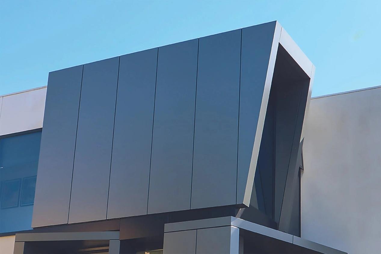 A well-designed thermal break curtain wall is foundational for high-performance façades in hot and humid climates. For projects in Saudi Arabia—where high solar radiation, elevated dew points, and extended cooling seasons drive large HVAC loads—specifying an effective thermal break curtain wall reduces conductive heat transfer, raises interior surface temperatures above dew point, and minimizes condensation-related damage to finishes. This article provides actionable design criteria, testable performance targets, installation and QA procedures, lifecycle economics, and a Saudi Arabia–focused case example for architects, façade engineers, contractors, and owners.





 Use this step-by-step checklist for procurement and specification: