
An installation drawing may appear complete, yet final work can still face coordination issues when site conditions differ from the information used during design. For 3D laser scanning, the purpose is to capture actual installation conditions before drawing review, fabrication, and site work move forward. A slab may sit at a different level from the drawing. A beam may reduce the ceiling void. Existing services may occupy the intended hanger zone. On a facade, wall positions, slab edges, openings, or interface conditions may also differ from the design information. These differences can affect panel dimensions, support locations, perimeter details, facade interfaces, and installation sequence.
3D laser scanning provides architects, contractors, and manufacturers with a digital record of the installation scope. It does not replace engineering review or final site verification, but gives the team a clearer reference for checking proposed layouts against actual conditions before production details are finalized.
For architectural metal systems, including metal ceilings and facade panels, 3D laser scanning helps teams review site conditions before finalizing drawings and planning installation. This article explains how scan data supports site reference creation, drawing coordination, and installation preparation.
1. Create a Reliable Site Reference with 3D Laser Scanning
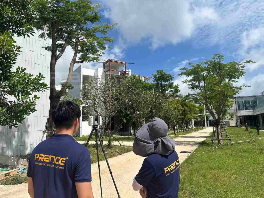
3D laser scanning creates a reliable site reference by capturing the existing space or building surface as detailed spatial data. During scanning, the equipment collects measurements from visible surfaces and combines them into a point cloud that represents the actual site conditions.
Capture Existing Conditions in a Point Cloud
Unlike traditional site measurement methods that record individual dimensions, 3D laser scanning captures the relationship between multiple elements within the same coordinate system. The scan records visible conditions such as ceilings, slabs, beams, walls, columns, openings, facade elevations, and other installation-related areas as a connected spatial reference.
The point cloud provides a digital record of the existing environment that teams can review before finalizing drawings. Differences between planned layouts and actual conditions, such as changes in levels, positions, or interfaces, become easier to identify during coordination.
Use Point Cloud Data for Drawing Review and BIM Coordination
The collected point cloud can be compared with reflected ceiling plans, elevations, sections, and 3D design models to check proposed layouts against the existing site. Architects, contractors, and manufacturers can use the reference to review dimensions, ceiling levels, facade panel geometry, installation relationships, and relevant exterior conditions before fabrication or installation planning.
A laser scan does not always need to be converted into a complete 3D model. For some reviews, direct point-cloud comparison provides enough information. When multiple disciplines need coordinated information, the scan data can support a shared BIM workflow.
For custom metal panel systems, the point cloud can also help confirm whether nominal panel dimensions, support geometry, and interface details suit the built condition before fabrication. This is particularly relevant for curved panels, large modules, irregular perimeters, and facade interfaces where extensive field trimming would affect appearance, installation time, or material use.
Project Example: Five-Star Hotel Development in Phuket
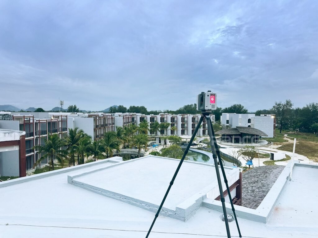
For a five-star hotel development in Phuket, PRANCE Design carried out multi-station 3D laser scanning during early design preparation. The scan covered the main hotel structures, public areas, and landscaped spaces, creating a coordinated point cloud reference within three days.
The site data supported refined design and production drawings for exterior cladding systems and a lobby strip ceiling. On a remote, multi-building hospitality development, this gave the team a clearer basis for reviewing site geometry, panel interfaces, and installation conditions before custom components moved toward fabrication.
2. Use 3D Laser Scanning to Review Drawings Against Actual Conditions

3D laser scanning provides a reference for checking whether installation drawings and models reflect the actual site. By comparing the scan data with proposed ceiling layouts or facade elevations, teams can identify differences in levels, support locations, interfaces, and surrounding conditions before those differences affect fabrication or installation planning.
Compare Proposed Layouts With Actual Site Conditions
The comparison starts with the relationship between the proposed metal system and the built environment. Reflected ceiling plans, elevations, sections, and 3D models can be reviewed against the point cloud to check ceiling levels, structural elements, MEP locations, support zones, perimeter conditions, facade openings, and facade interfaces.
In practice, the scanned conditions may not fully match the original design information. A beam may sit lower than expected. Existing services may occupy a planned ceiling zone. Walls or columns may vary from the assumed layout. On an exterior scope, slab edges, window positions, substrate conditions, or other facade interfaces may require review before facade panels are released. These differences do not always require major changes, but they need to be identified before drawings are finalized.
|
Actual Site Condition |
Drawing Review Check |
Possible Coordination Issue |
|
Slab level or beam depth differs |
Ceiling elevation, facade datum, and section details |
Confirm system level or support arrangement |
|
Existing MEP location differs |
Ceiling layout and service coordination |
Review conflicts with ceiling components |
|
Wall, column, opening, or slab-edge position varies |
Perimeter, edge, and facade interface details |
Check panel dimensions, closure conditions, and interface alignment |
Update Drawings Before Fabrication and Installation Planning
Scan-based drawing review helps confirm that the proposed metal system information matches the installation environment. When differences are identified, the relevant drawings can be updated, affected details can be coordinated, and the project team can confirm the next steps before fabrication or installation planning.
The purpose is not to eliminate every site adjustment. It is to resolve measurable differences early and carry the agreed changes into the controlled drawing set before affected panels or support components are released for fabrication.
3. Use Scan Findings for Installation Planning

Scan findings become useful on site when they are reflected in the installation plan. The plan identifies where the system starts, how levels and setting-out lines are established, where supports can be installed, and which interfaces need coordination before panels are fabricated and installed.
Set Out Levels and Confirm Support Locations
The reviewed drawings establish the working ceiling level, facade datum, and main setting-out lines. They also show where hangers, carriers, brackets, rails, and other supports can be installed without conflicting with existing conditions.
For a metal ceiling, these checks affect panel direction, joint alignment, closure dimensions, and the visual consistency of the finished surface. For facade panels, they affect elevation setting-out, panel module alignment, opening interfaces, and the relationship between the panel system and adjacent construction. A small adjustment near a perimeter or facade edge may have little impact on drawings but become highly visible after installation.
In complex zones, the review can help the team define a practical starting point, panel direction, joint alignment, and closure strategy before installation begins. This is useful where ceiling modules meet glazing, walls, services, or where facade panels need to align with openings, slab edges, and adjacent materials.
Coordinate Access and Installation Sequence
Some areas require work from other trades before the metal system can be closed. An access opening may need to remain available until equipment testing is complete. A perimeter detail may need to wait for a wall finish, glazing interface, service installation, or the completion of an adjacent facade interface. A complex ceiling or facade zone may require a site check after the first support line is set out.
For oversized panels or prefabricated modules, the same site reference can support an early review of delivery routes, lifting access, temporary support locations, and available working space. Installation and lifting parties still need to confirm the final method, equipment, and safety requirements; scan data provides the spatial reference rather than a substitute for those approvals.
The installation sequence needs to reflect these conditions. Contractors can use the plan to coordinate access, lifting, temporary protection, and inspection points around the ceiling or facade package. This helps avoid removing installed panels to correct issues that could have been coordinated earlier.
Conclusion: From Scan Data to Installation Planning
3D laser scanning helps connect site conditions with the decisions required before installation:
3D scan → point cloud or model reference → drawing review → coordination decisions → installation plan
For commercial architectural metal systems, accurate site information is only one part of the process. The design information also needs to be developed into coordinated drawings and production-ready details before fabrication begins. Relying only on standard product supply may not address the coordination required between site conditions, drawings, facade or ceiling interfaces, and manufacturing.
PRANCE design team supports this process through site measurement, design deepening through drawings, and production preparation for architectural metal systems, including metal ceilings and facade panels. A coordinated workflow helps project teams move from verified site conditions to manufacturable panel systems.
If your project requires support from site measurement through fabrication preparation, discuss the required information and coordination process with the PRANCE team.
FAQ
Does every laser scan need to be converted into a 3D model?
No. A point cloud may be sufficient for reviewing reflected ceiling plans, facade elevations, sections, support zones, and local interfaces. A 3D model is more useful when several trades need to coordinate the same area or when the project needs revised geometry to be shared across a BIM workflow. The required output should match the coordination task.
How should scan findings be recorded during drawing coordination?
The project team should record the issue, affected drawing area, agreed action, and responsible party. Some findings lead to revised panel dimensions or support details. Others require an RFI or confirmation from another trade. Linking the decision to the controlled drawing set prevents fabrication and installation teams from working from different assumptions.
When should a scanned installation area be checked again?
Recheck the area when later work changes a condition that affects the metal system. Examples include revised MEP routing, structural modifications, new wall finishes, changes to access openings, or revised facade interfaces. The scale of the recheck should match the affected area, but it should happen before dependent ceiling or facade work is released or installed.


