Designing for Acoustic Performance in Auditoriums Using Layered Perforated Metal and Absorbers — auditorium acoustic ceiling
Introduction
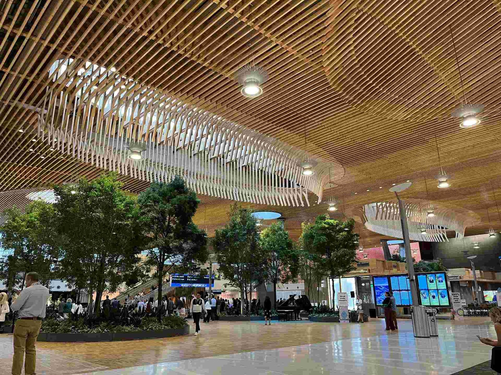
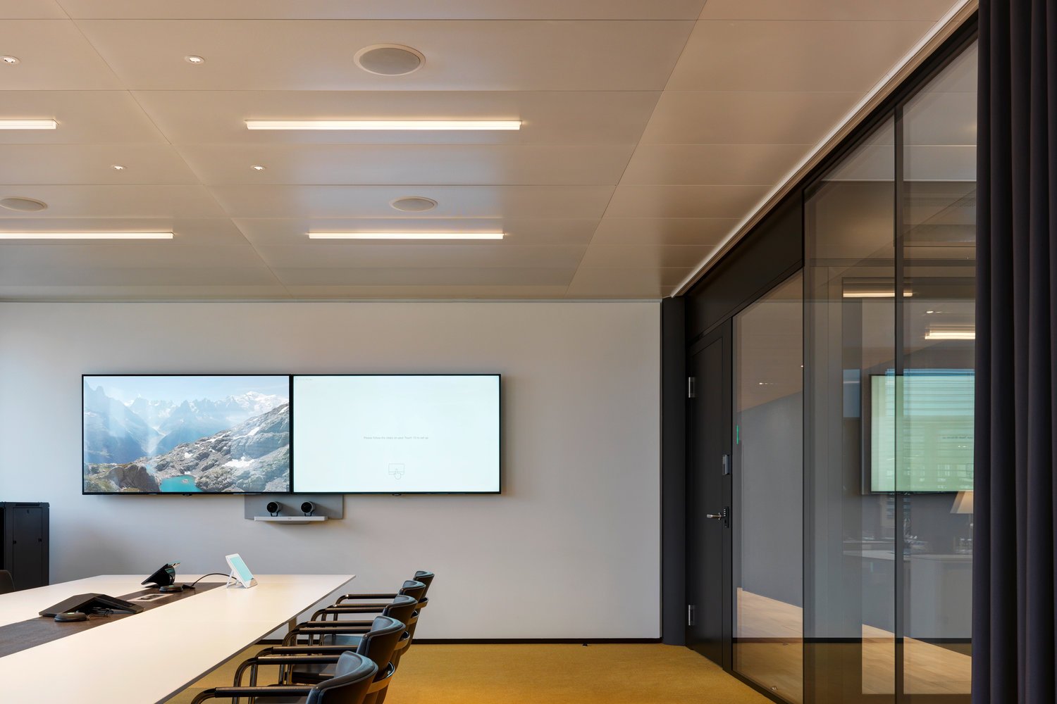
An effective auditorium acoustic ceiling is central to speech intelligibility, musical clarity, and audience comfort. Designers and specifiers must reconcile aesthetic demands with measurable acoustic targets, fire safety, and long-term serviceability. Layered systems that combine perforated metal facings with tuned absorbers and controlled cavity depths deliver a robust, maintainable solution that supports integrated lighting, HVAC, and access requirements. This article outlines technical selection criteria, installation best practices, testing protocols, and actionable specification guidance for B2B stakeholders.
auditorium acoustic ceiling — perforated metal profiles
Perforated metal panels function as both the architectural finish and the protective skin for absorbers. Key variables include material (aluminum, galvanized steel), perforation geometry (round, slotted, micro-perf), and open-area percentage. Typical open-area ranges for acoustic applications are 10%–25%; smaller holes with higher cavity depth improve low-frequency performance. Aluminum is often preferred for its low weight, corrosion resistance, and compatibility with PVDF and anodized finishes.
Absorber placement and cavity depth
Absorber selection (mineral wool, fiberglass, basalt wool, or engineered acoustic foam) should be driven by target frequencies. Cavity depth is the most effective tuning parameter: shallow cavities (25–75 mm) address mid-to-high frequencies, while deeper cavities (100–300 mm) or tuned resonators address bass. Combining surface absorption with localized deep cavities near stage and rear-wall zones yields balanced frequency control.
Finish, durability, and fire rating
Specify coating systems and fire classifications early. PVDF or fluoropolymer coatings provide long-term color stability. Absorbers must meet local fire standards—non-combustible mineral wool is a common choice in public assembly spaces. Include splash and moisture resistance for auditoria with variable HVAC loads. Manufacturing quality control should document coating adhesion, perforation tolerance, and absorber lot density to guarantee consistent acoustic performance.
auditorium acoustic ceiling: installation and maintenance
Correct sequencing reduces rework. Install primary structure, then integrate heavy services (suspension lines, cable trays, sprinklers). Confirm coordinate drawings for light fixtures and diffusers before installing acoustic panels. Use adjustable hangers and resilient mounts to minimize structure-borne vibration and flanking paths. For systems with built-in access, ensure removable panels are oriented for service zones.
Inspection, cleaning and long-term maintenance
A planned maintenance regime preserves acoustic properties. Inspect absorbers after any moisture event and perform scheduled visual inspections every 3–5 years. Cleaning perforated metal is straightforward—vacuuming, low-pressure washing, or gentle wiping—while avoiding solvents that degrade coatings. Track absorber replacement cycles and document NRC and RT60 measurements after replacements.
Access strategies and serviceability
Design for modularity: lay-in panels, hinged sections, and removable clouds facilitate access to lighting, AV, and HVAC. Define access module sizes (e.g., 600×600 mm grid or rectangular trapdoors) in the specification. For large auditoria, locate access points in non-critical acoustic zones to avoid visible repairs affecting sightlines.
Technical performance and testing
Acoustic metrics: NRC, RT60, and Speech Transmission Index
Quantify goals using accepted metrics. NRC (ASTM C423) indicates average absorption; RT60 measures reverberation decay (ISO 3382 / ASTM E2235); STI or C50/C80 assess speech clarity for spoken-word versus music. Target values depend on room use: speech-focused halls: RT60 ≈ 0.8–1.2 s, music-focused halls: RT60 ≈ 1.5–2.0 s. Use these numbers to select absorber thickness, density, and cavity depth.
Field testing and commissioning
Commissioning should include before-and-after RT60 tests, impulsive-response measurements, and STI evaluations in occupied and unoccupied states. Verify installed open area, cavity depth, and absorber density against shop drawings. Require the contractor to provide a commissioning report with raw data and corrective actions if deviations exceed 10% of modeled predictions.
Modeling and low-frequency strategies
Predictive modeling (geometric acoustics and finite-element modal analysis) helps target low-frequency issues that classic absorption metrics miss. For problematic bass modes, incorporate tuned Helmholtz absorbers, perforated resonator panels, or distributed cavity arrays. Use measured transfer functions during commissioning to validate modeled tuning.
Define target acoustic metrics (RT60 by octave band, STI targets).
Specify perforation pattern, open-area percentage, and panel module size.
Detail absorber material, density (kg/m³), thickness, and fire rating.
Include cavity depth and any tuned resonator requirements.
Require shop drawings, mock-up sign-off, and factory QC documentation.
Integration with building systems
Coordinate ceiling penetrations for lighting, sprinklers, and diffusers. Specify sealed cut-outs and acoustic collars for MEP penetrations. Where plenum air movement could degrade absorbers, specify sealed trays or moisture-resistant materials. Coordinate with structural engineers for load paths when integrating heavy luminaires or AV rigs.
Manufacturing and quality control best practices
Manufacturers should deliver certificates for perforation verification, coating adhesion (ASTM D3359 or similar), and absorber lot density testing. Insist on ±1 mm panel dimensional tolerance for modular systems and traceability for metal and absorber batches. Provide factory-finished panels and pre-punched mounting locations to reduce site labor and preserve finish quality.
Project case example: Layered system in a mid-size theater
Design parameters and predicted performance
A hypothetical 650-seat theater (approx. 9,000 m³) aimed for mixed programming: speech and chamber music. Targets: RT60 = 1.0 s for speech, 1.6 s for music; STI improvement >0.10. Designers selected 15% open-area micro-perf aluminum, 75 mm mineral wool, and 200 mm deep tuned cavities in rear and ceiling cloud zones. Modeling predicted a 20–30% RT60 reduction in critical bands.
Construction notes and outcome
A pre-installation mock-up validated sightlines, finish, and access. Installation used resilient clip hangers and a grid of removable panels to allow under-ceiling service. Post-installation tests measured RT60 of 1.05 s for speech conditions, and STI improved by 0.12 points versus the pre-refit baseline. The project timeline included 2 weeks for mock-up sign-off and 10 weeks for ceiling supply and installation.
Lessons learned and cost-benefit analysis
Investing in mock-ups and factory QC reduced site punchlist time by 35% in this scenario. Additional upfront cost (approx. 6–8% of ceiling budget) for deeper cavities and tuned resonators yielded measurable acoustic gains and reduced remedial works. Lifetime savings are realized through targeted replacements of absorbers rather than full panel swaps.
Addressing common objections and solutions
Aesthetic concerns vs acoustic function
Objection: Perforated metal looks industrial.
Response: Use micro-perf, custom paint finishes, and concealed reveal profiles to achieve refined finishes. Acoustic performance can be retained while meeting high-end design expectations.
Low-frequency performance worries
Objection: Panels don’t absorb bass well.
Response: Add depth with localized cavities, use denser absorbers, or integrate tuned Helmholtz panels. Quantify improvements with modeling and on-site testing.
Fire and health safety questions
Objection: Absorbers pose fire or indoor air quality risks.
Response: Specify non-combustible mineral wool or certified low-VOC foams and require manufacturer test reports. Include over-time inspection clauses and replace absorbers after moisture or contamination events.
Actionable recommendations for specifiers and decision-makers
Establish acoustic targets early and specify them numerically in contracts
Require pre-installation mock-ups that include finish, perforation, and access mock-ups.
Demand production test certificates and a shop drawing sign-off process.
Include commissioning tests (RT60, STI) as part of practical completion.
Plan maintenance: accessible panels every 20–30 m² and absorber inspections every 3–5 years.
Comparison table: common layered system choices
System
Best for
Typical cavity depth
Micro-perf aluminum + mineral wool
Balanced mid/high control
50–200 mm
Slotted perforation + dense wool
Low-frequency emphasis
100–300 mm
Metal + engineered foam panels
Tight spaces, quick install
25–100 mm
Deep-dive: perforation geometry and acoustic behavior
Perforation geometry is more than an aesthetic choice—hole diameter, spacing, and pattern fundamentally control the acoustic coupling between the face and absorber. Typical micro-perf diameters range from 0.8–2.0 mm; larger holes (3–8 mm) with higher open area increase coupling for mid frequencies. Slot perforations provide directional absorption that can be useful near stage overhangs. When specifying, include hole diameter, hole center spacing, and edge distance tolerances in the contract to avoid field deviations that alter performance.
Vibration and flanking control
Acoustic ceiling systems can be a path for structural-borne vibration if not isolated. Use resilient hangers or neoprene isolation pads at suspension points, and consider decoupling panel joints where loudspeaker or mechanical vibration would otherwise transmit to sensitive surfaces. For auditoria with adjacent rehearsal spaces, model flanking transmission as part of the acoustic brief and include resilient mounts and perimeter sealing in the design.
Costing and lifecycle considerations
Initial installed cost varies by material and complexity. As a guideline:
• Basic micro-perf + mineral wool: moderate initial cost, low maintenance.
• Tuned resonator arrays: higher initial cost, targeted low-frequency gains.
• Engineered thin panels: lower install cost, possible shorter service life.
Factor lifecycle costs: accessibility reduces labor for replacements; specifying replaceable absorbers can halve lifecycle expenses compared to systems requiring whole-panel replacement.
Expanded actionable step-by-step checklist
Program phase: define room uses and acoustic targets (RT60 by octave, STI).
Concept phase: select candidate panel types and absorber materials; build a 1:1 mock-up.
Design development: coordinate penetrations, finalize cavity depths, and integrate fire and structural requirements.
Tender: require manufacturer QC documentation, sample finishes, and mock-up sign-off as part of the contract.
Construction: enforce tight tolerances for suspension geometry; verify cavities and absorber density prior to close-in.
Commissioning: perform RT60, STI, and frequency-band verification; document deviations and corrective actions.
Handover: provide maintenance manual, supplier contacts, and replacement part numbers.
Lifecycle: schedule inspections and absorber replacement cycles based on environment and occupancy.
Manufacturing quality control (expanded)
Best-practice QC includes a documented chain of custody for metal and absorber batches, dimensional inspection reports, and adhesion and abrasion testing of finishes. For anodized aluminum, specify anodic layer thickness (µm) and dye stability; for PVDF coatings, require accelerated weathering cycles and salt spray testing when relevant. Manufacturers should offer lot traceability so a failing batch can be isolated and replaced without a full system rework.
Closing thoughts for decision-makers
An auditorium acoustic ceiling built with layered perforated metal and tuned absorbers is a versatile, long-term solution for assembly spaces. When specified with clear acoustic targets, rigorous QC, and an integrated access strategy, these systems deliver predictable acoustic outcomes, visual flexibility, and reasonable lifecycle costs. Engage acoustic consultants early, require mock-ups, and make commissioning and maintenance contractual deliverables to protect design intent and public safety.
FAQ
Q1: What exactly is an auditorium acoustic ceiling?
A1: An auditorium acoustic ceiling is a ceiling system engineered to control reverberation and improve speech and music clarity. Typical systems use a perforated metal facing with absorptive material behind it and tuned cavities to target specific octave bands, meeting RT60 and STI specifications for auditoria.
Q2: How do I determine the right perforation open area?
A2: Choose open-area percentage based on desired absorption bandwidth; 10–25% is common. Combine open area with absorber thickness and cavity depth to meet RT60 targets. Modeling and mock-ups validate the final selection for the auditorium acoustic ceiling.
Q3: Can I fit an acoustic ceiling in shallow plenum spaces?
A3: Yes. Use micro-perf with higher open area and denser absorbers or engineered thin absorbers. Consider distributed small resonators if low-frequency control is needed. Shallow options can still meet targets if modeled correctly for the auditorium acoustic ceiling.
Q4: What testing is required after installation?
A4: Required tests typically include reverberation time (RT60), STI or clarity measurements, and verification of installed open area and cavity depth. These confirm that the auditorium acoustic ceiling meets the contractual acoustic metrics and design intent.
Q5: How should I budget for maintenance and lifecycle?
A5: Budget for inspection every 3–5 years and absorber replacement cycles (8–15 years depending on environment). Include access panels and service strategy to minimize lifecycle costs and sustain the auditorium acoustic ceiling performance.
Looking for custom-designed ceilings, walls, or facades to elevate your project? Explore PRANCE Design’s integrated design and manufacturing solutions, and create the perfect fit for your architectural needs today!

 An effective auditorium acoustic ceiling is central to speech intelligibility, musical clarity, and audience comfort. Designers and specifiers must reconcile aesthetic demands with measurable acoustic targets, fire safety, and long-term serviceability. Layered systems that combine perforated metal facings with tuned absorbers and controlled cavity depths deliver a robust, maintainable solution that supports integrated lighting, HVAC, and access requirements. This article outlines technical selection criteria, installation best practices, testing protocols, and actionable specification guidance for B2B stakeholders.


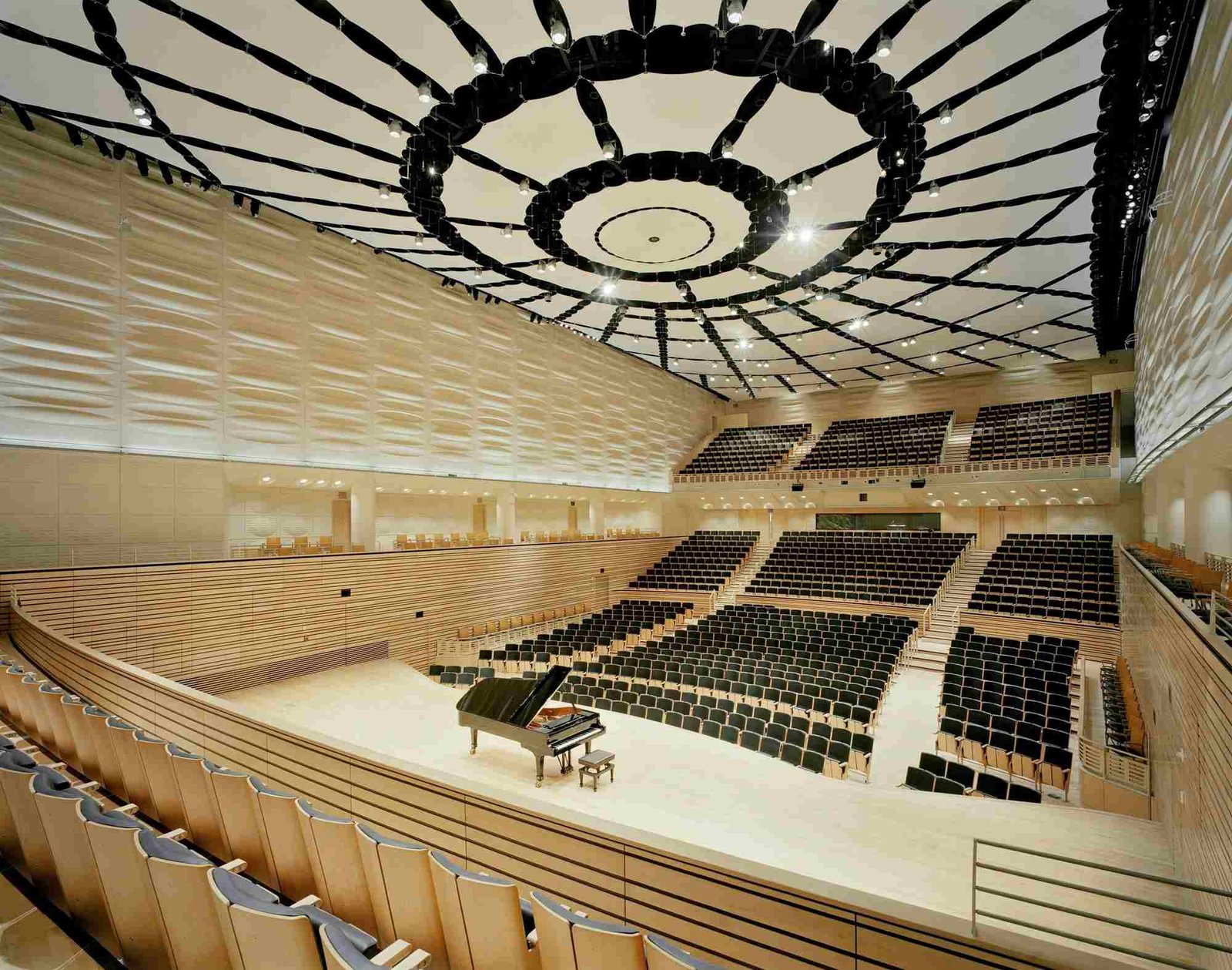


 Perforation geometry is more than an aesthetic choice—hole diameter, spacing, and pattern fundamentally control the acoustic coupling between the face and absorber. Typical micro-perf diameters range from 0.8–2.0 mm; larger holes (3–8 mm) with higher open area increase coupling for mid frequencies. Slot perforations provide directional absorption that can be useful near stage overhangs. When specifying, include hole diameter, hole center spacing, and edge distance tolerances in the contract to avoid field deviations that alter performance.

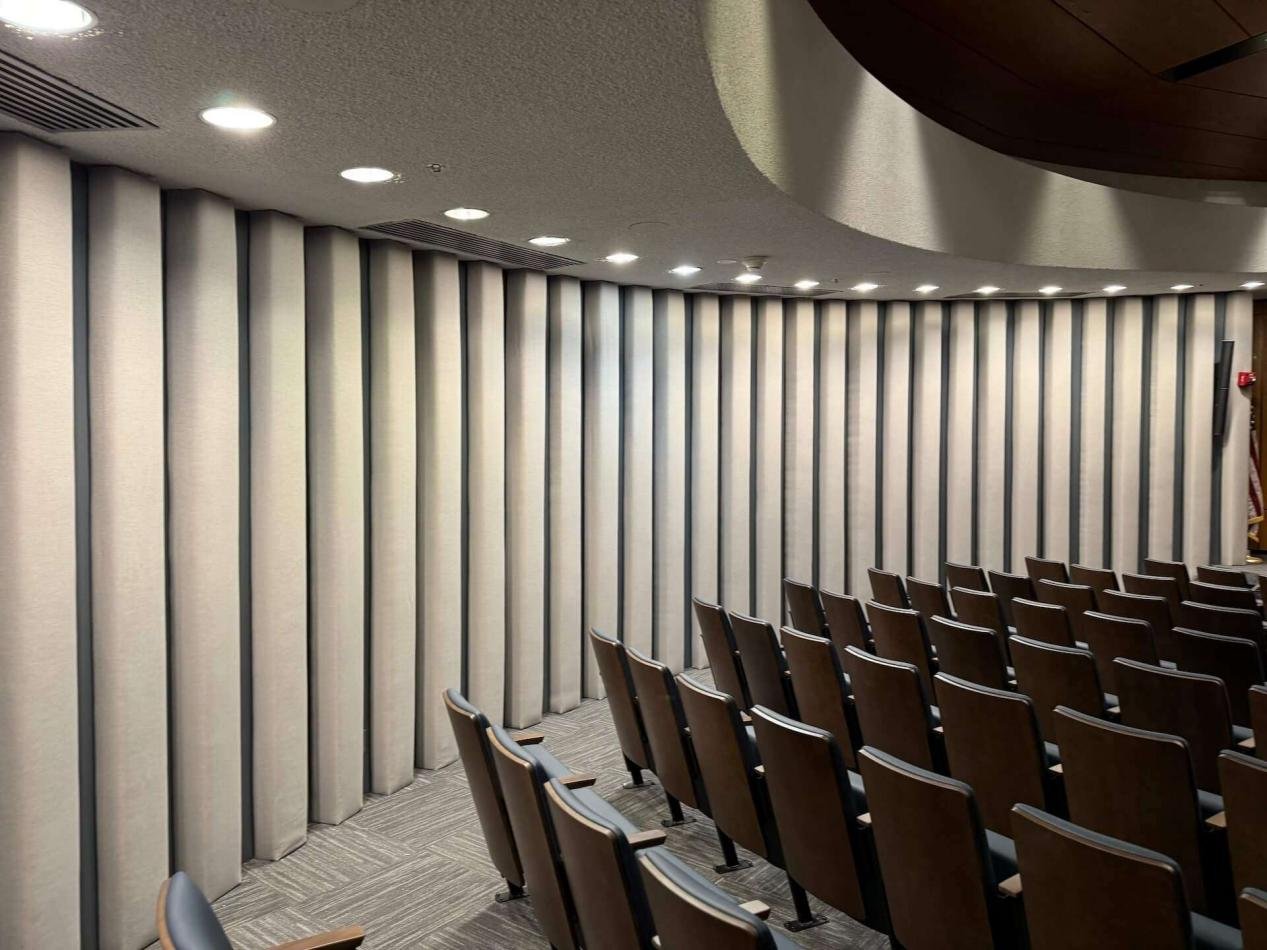 Best-practice QC includes a documented chain of custody for metal and absorber batches, dimensional inspection reports, and adhesion and abrasion testing of finishes. For anodized aluminum, specify anodic layer thickness (µm) and dye stability; for PVDF coatings, require accelerated weathering cycles and salt spray testing when relevant. Manufacturers should offer lot traceability so a failing batch can be isolated and replaced without a full system rework.
 An auditorium acoustic ceiling built with layered perforated metal and tuned absorbers is a versatile, long-term solution for assembly spaces. When specified with clear acoustic targets, rigorous QC, and an integrated access strategy, these systems deliver predictable acoustic outcomes, visual flexibility, and reasonable lifecycle costs. Engage acoustic consultants early, require mock-ups, and make commissioning and maintenance contractual deliverables to protect design intent and public safety.