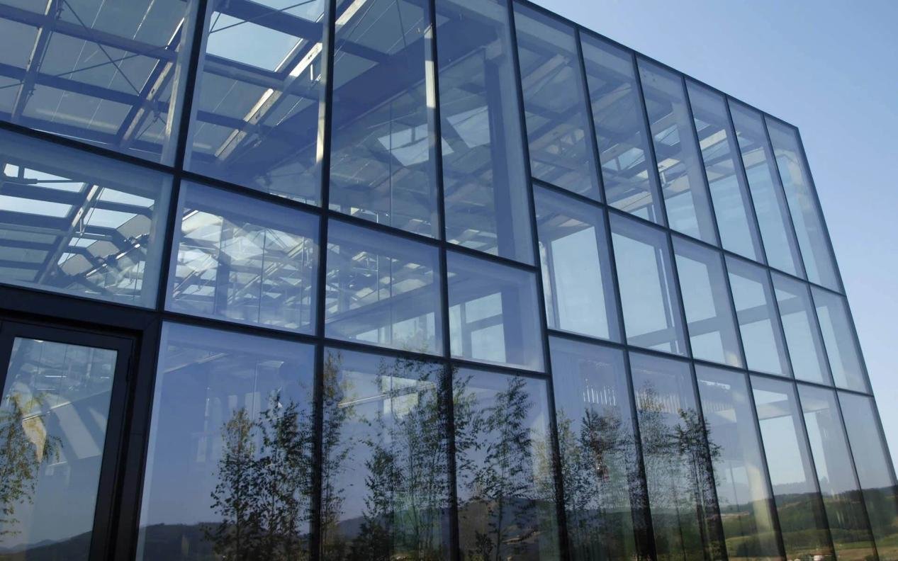
The Stick System Curtain Wall is a widely used, component-based façade approach where vertical mullions and horizontal transoms are assembled on site and glazed in sequence. This configuration provides design flexibility, simplifies logistics for phased projects, and lowers initial fabrication lead times compared with fully unitized façades.
Market opportunity and scope
For architects, contractors, and façade engineers working on commercial and institutional buildings, the Stick System Curtain Wall offers a pragmatic balance of performance and cost. It is especially competitive for mid-rise and certain high-rise envelopes where site access, sequencing constraints, or varied panel sizes make factory-assembled unitized systems less practical. The system supports mixed-use elevations, varying spandrel treatments, and integration of operable vents or louvers.
Stick System Curtain Wall: Technical Features
Stick System Curtain Wall mullion and transom design
The primary load-bearing elements are extruded aluminum mullions and transoms. Mullion design controls gravity loads, lateral wind loads, and deflection; transoms support glazing and transfer loads to mullions. Thermal breaks—typically polyamide or reinforced polymer—interrupt conductive paths and reduce thermal bridging. Engineers size sections to meet project-specific wind pressures and deflection limits (commonly L/120 to L/240 for glazing). Typical connection details include splines and bolted joints with controlled bolt patterns and fastener grades chosen to resist shear and tensile demands.
Designers must consider glass bite, edge clearance, and allowable stresses for laminated or tempered panels. Where operable vents or heavy spandrel infills are used, transom span limits and anchorage reinforcement should be confirmed with structural calculations. Use finite element or hand-calculated checks for critical mullions facing high wind exposures.
Stick systems accept a broad range of glazing from single-pane tempered glass to high-performance insulating glass units (IGUs), laminated safety glass, and low-emissivity coatings. The system allows tailored glazing by elevation: for example, using double-glazed low-e units on solar-exposed façades and high-visibility laminated assemblies at pedestrian-level storefronts. To control acoustic performance, specify asymmetrical IGUs with different glass thicknesses and damping interlayers. Spacer selection and cavity gas fill (e.g., argon) further refine thermal and acoustic outcomes.
When glazing large spans, consider edge restraint and glass thickness coordination to limit glass stresses due to wind and thermal gradients. Specify minimum edge engagement and setting blocks to prevent point-loading and premature seal failure.
Secondary components and weatherseal system
Weather performance depends on robust gaskets, pressure plates, edge blocks, and back-bedding sealants. Designers normally specify drainage paths behind pressure plates, through-mullion weeps, and redundancy in seals to manage water under extreme wind-driven rain. Typical acceptance tests include ASTM E283 (air infiltration), ASTM E331 (water penetration), and ASTM E330 (structural performance under wind). Drainage cavities must be sized to accommodate expected water volumes and include accessible cleanouts. Proper selection of sealant chemistry (silicone vs. polyurethane) should reflect substrate compatibility, UV exposure, and movement range over the expected service temperature range.
Design Considerations for Curtain Wall Systems
Performance targets and load paths
Set explicit performance metrics early: design wind pressures (Pa), deflection limits (mm), seismic movement allowances, and façade acoustic targets (STC or OITC). The stick approach is adaptable to unusual bay widths and opening patterns; however, the design team must coordinate anchor locations and transfer loads carefully to avoid overloading the primary structure. For taller buildings, consider inter-story drift and specify slip-type anchors where differential movement is probable.
Include criteria for live-load and maintenance loads (window cleaning rigs), and ensure the façade design does not impose excessive concentrated loads onto secondary structure. Where rainscreen cladding or integrated shading devices are used, confirm load transfer and fixings early in the design process.
Thermal and condensation control strategies
Specify continuous thermal breaks and thermal-blocked anchorage systems to mitigate bridging. Use whole-unit U-value targets and project-specific dew-point calculations to avoid interstitial condensation. For cold climates, include warm-edge spacers and low-conductivity anchors; in hot climates, aim for SHGC reduction and solar control coatings. Consider insulated pressure plates or thermal-cap covers to limit conductive paths in visible metal sections.
Thermal modelling should be run for critical façades (south and west exposures) and include transient effects where diurnal temperature ranges are large. Provide condensation risk assessments for cavity and edge details as part of the shop drawing review.
Integration with building structure and tolerances
Define construction tolerances for slab edge, column line, and floor-to-floor offsets. Stick systems tolerate some site variation but require accurate datum lines and anchor placement. Include adjustable anchors with slotted holes, shims, and setting blocks to manage vertical and horizontal misalignment. For retrofit projects, incorporate tolerance rings and shim packs to accommodate irregular as-built conditions. Coordinate MEP penetrations, balcony interfaces, and parapet transitions in the early design to avoid late-stage rework.
Installation typically follows a logical sequence: install continuous vertical mullions, fix horizontal transoms or spiders, install glazing units, then attach pressure plates and caps. This on-site sequencing enables concurrent interior work and phased exterior completion, offering cash-flow advantages on larger projects. It also reduces factory capacity requirements and allows design adjustments during installation. Where site access is constrained, pre-assembled transom packs can reduce cranage cycles.
Anchoring, sealant application, and on-site QA
Anchors should be specified with shear and pull-out capacities aligned with calculated façade reactions. Chemical or mechanical anchors have different acceptance criteria; choose anchors tested to manufacturer’s specifications and applicable codes. Sealant joint design must accommodate expected movement (thermal and seismic) and use backer rods to control depth. Implement daily QA, including dimensional checks, torque logs for fasteners, and adhesive cure verification. Use non-destructive field tests for anchor torque and maintain photographic documentation for critical assemblies.
A documented remediation protocol for discovered defects avoids project delays: remove and replace compromised gaskets, re-drill and re-anchor using approved methods, and re-test affected zones. Require contractor to maintain a defect register and corrective action logs to ensure traceability and continuous improvement.
Logistics, safety, and contractor coordination
On-site assembly increases crane lifts and handling. Contractors must coordinate staging zones, glazing protection, and fall-arrest plans. Pre-delivery inspections of shop-fabricated components reduce rework; require suppliers to prepack fittings and gasket kits for each bay. Train installation crews on manufacturer-specific gasket seating and pressure plate torque to prevent glazing edge damage. Plan for just-in-time deliveries to minimize on-site storage and avoid damage in congested urban sites.
Performance, Testing, and Maintenance
Industry-standard test methods and acceptance criteria
Specify objective tests: ASTM E283 for air infiltration, ASTM E331 for water penetration, and ASTM E330 for structural wind performance. When possible, require test pressures to match or exceed project design pressures (for example test at 1.5× design wind pressure) and include allowable leakage rates (e.g., ≤ 0.3 cfm/ft² at a specified pressure). For thermal claims, request validated whole-unit U-values and, where applicable, NFRC-equivalent performance documentation.
In contracts, require recent laboratory test certificates (within 36 months) and allow for witnessed repetition of tests on site if material or detailing changes occur. Include acceptance tolerances (e.g., maximum allowable deflection limits and pass/fail leakage rates) and state remedies for failure, such as replacement of assemblies or additional sealing works at supplier expense.
Planned maintenance and lifecycle cost considerations
Routine maintenance includes inspecting gaskets and drainage, scheduled sealant replacement (typically 10–20 years depending on exposure), and annual cleaning of weep and drainage channels. Lifecycle costing should include scheduled gasket and sealant replacement and potential re-coating intervals for exposed finishes. For high-rise assets, plan rope access inspections or integrated sensor checks for weep performance to limit costly scaffolding.
Budget for predictable maintenance items at design stage—these costs often dominate long-term operating budgets. Include spare gasket kits and a small inventory of finished caps and pressure plates for rapid repair.
Durability, finishes, and corrosion resistance
Specify finish systems—powder coat or Class I fluoropolymer (AAMA 2605-equivalent) for long-term color retention. For coastal projects, require anodic thickness, marine-grade fasteners, and duplex-coated anchors. Manufacturing quality control should include anodizing thickness checks, salt spray or cyclic corrosion testing where appropriate, and paint adhesion pull tests. Insist on mill and test certificates for alloys and hardware to manage risk.
Specification Checklist and Actionable Recommendations
Specification checklist for decision-makers
Define wind, seismic, and deflection criteria numerically and include test pressures.
Require ASTM test acceptance levels and set quantifiable leakage/water thresholds.
Specify whole-unit thermal targets (U-value, SHGC) and acoustic goals (STC/OITC).
Mandate mock-up testing and pre-installation sign-off procedures with third-party witnessing.
Set corrosion and finish standards specific to project exposure, including specified coating systems and thicknesses.
Sample specification clause (example): “Curtain wall assemblies shall comply with ASTM E283, E331, and E330 at test pressures equal to or greater than project design pressures. Whole-unit U-value shall not exceed 1.8 W/m²·K. Mock-up shall be constructed and tested prior to production release.”
Step-by-step procurement and installation roadmap
Program phase: set performance targets, façade modules, and budget allowances.
Design phase: coordinate anchors, movement joints, and service penetrations with structural and MEP teams.
Tender phase: prequalify vendors; require shop drawings, material certificates, and recent test reports.
Construction phase: execute a full-size mock-up and witnessed tests before mass installation; maintain daily QA logs.
Case Study: Mid-Rise Office Block Applying Stick System Curtain Wall
Project brief and constraints
A 12-storey office block in a temperate urban setting required a façade that allowed staggered fit-out for multiple tenants and reduced early-stage fabrication expense. The client prioritized thermal performance, visual uniformity, a 20-year service life, and minimal disruption to neighboring properties.
Design solution and execution
The design team specified a Stick System Curtain Wall with thermally-broken aluminum mullions, 28mm double-glazed IGUs with low-e coatings, and warm-edge spacers. Mullion anchor assemblies accommodated ±15 mm site tolerance. A factory pre-assembly of transom-to-mullion sub-assemblies reduced on-site fitment time by 18%. A full-scale mock-up passed ASTM E331 at 75% higher pressure than the design wind load to provide an extra performance margin.
Outcomes and metrics
The façade met target whole-unit U-values of 1.6 W/m²·K (approx. 0.28 Btu/h·ft²·°F) and achieved ASTM E283 air leakage well under common thresholds. Phased installation saved about 8% in immediate cash flow needs and reduced the need for storage by delivering components just-in-time. Factory pre-assembly of subcomponents reduced site labor hours by an estimated 12%, and the mock-up-based commissioning avoided costly remedial work. Owner expectations for visual uniformity and thermal comfort were met within budget.
Cost, Scheduling and Procurement
Cost drivers and trade-offs
Key cost drivers for stick systems include raw material prices (aluminum alloys), glazing specification (IGU thickness and coatings), anchor complexity, and on-site labor rates. While unitized systems may offer reduced site labor costs, they often incur higher factory costs and longer lead times. Evaluate the whole-life cost: a modest increase in initial specification (better thermal break, warm-edge spacers) often yields energy savings and lower lifecycle replacement costs.
Procurement strategy and contracting tips
Use performance-based specifications rather than prescriptive shop drawings in early tender stages to encourage innovation. Require supplier prequalification with evidence of recent mock-up tests and ISO 9001-based quality systems. Consider milestone-based payments tied to mock-up acceptance, delivery milestones, and final performance testing to align supplier incentives.
Addressing Common Objections and Clear Solutions
Objection: slower installation and weather exposure
Solution: Use pre-finished components, staged installation with temporary weather barriers, and mandate mock-up validation for weatherseal details. Employ protective edge guards during glazing insertion.
Objection: variable on-site quality
Solution: Contractually require supplier field supervision, calibrated setting templates, and daily QA reports. Use hold-points for critical activities such as anchor installation and first-module glazing.
Objection: insufficient thermal performance
Solution: Require explicit whole-unit U-values and spacer/thermal break details in specifications. Request validated thermal models and encourage the use of argon fills and warm-edge spacers where cost-effective.
Manufacturing and Quality Control Best Practices
Factory QC procedures
Manufacturers should provide documented extrusion QC, alloy certificates, anodize and paint test records, and dimensional inspection reports. Implement statistical process control on critical dimensions to reduce variation and ensure repeatability.
Incoming inspection and pre-assembly tests
On receipt, perform incoming inspection for profiles, gaskets, glass units, and hardware. Conduct pre-assembly checks for fit and finish and require factory mock-up tests (water and air) prior to shipment.
Mock-ups, witness tests, and release criteria
Require a full-scale mock-up tested to contract-specified pressures with third-party witness and sign-off. Components should be released for shipment only after mock-up acceptance and documentation of QC results.
Conclusion
Executive summary
The Stick System Curtain Wall is a flexible, cost-conscious façade solution that suits many project types when properly specified and quality-controlled. It offers phased installation benefits and glazing flexibility while meeting rigorous performance standards when tested per ASTM methods.
Next steps for specifiers and procurement teams
Include unambiguous performance criteria in contracts, mandate mock-ups and ASTM testing, document manufacturing QC, and plan a preventative maintenance program. These measures reduce lifecycle costs and ensure the façade delivers long-term value.
Looking for custom-designed ceilings, walls, or facades to elevate your project? Explore PRANCE Design’s integrated design and manufacturing solutions, and create the perfect fit for your architectural needs today!